Offshore Wind Modeling
This example includes configs to run a reV wind analysis for a small test extent off the east coast. This example is only meant to demonstrate how to set up an offshore wind LCOE analysis using reV + NRWAL. Note that some inputs and configurations are purely fictitious and should not be used in a real analysis. For example, this test case models the same turbine onshore and offshore. The substructure for the offshore turbines are also assumed to always be a floating semi-submersible which is not realistic, especially for shallow waters.
reV Offshore Module Description
The pipeline includes the reV-NRWAL module (replaced the historical reV-offshore module), which is run after the generation module. The offshore module takes the gross generation (gross capacity factor, set offshore turbine losses to zero!) and uses NRWAL to calculate generation losses and LCOE.
Example NRWAL configs slightly modified for use with reV can be seen in this example. The primary modification for usage in reV is that NRWAL typically calculates the grid connection cost with the “grid” equations. Currently, reV uses NRWAL to calculate the array and export (to shore) tranmission costs and then uses the supply curve transmission cost tables to calculate the grid connection costs.
Treatment of Offshore Points in Supply Curve
Offshore points are treated identically to onshore points in the supply curve (not run here). All resource pixels maintain their source resolution (usually the 2km WTK resolution) until the reV aggregation step, where exclusions are applied and the data is aggregated up to the supply curve grid. Supply curve tranmission cost tables must include transmission costs for offshore supply curve points. There is no seperate or special handling of offshore supply curve transmission connection.
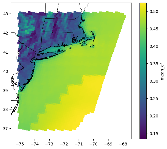
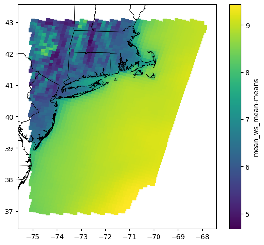
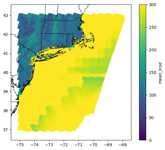
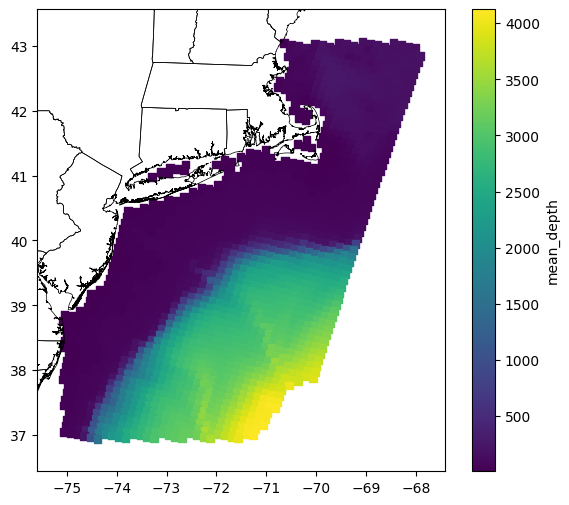
Plots of the Example Offshore Output