Preprocess
Generate STL patch mesh
Boundaries may be specified with the surfaceToPatch utility in OpenFOAM, based on STL files that can be generated with
python applications/write_stl_patch.py -v
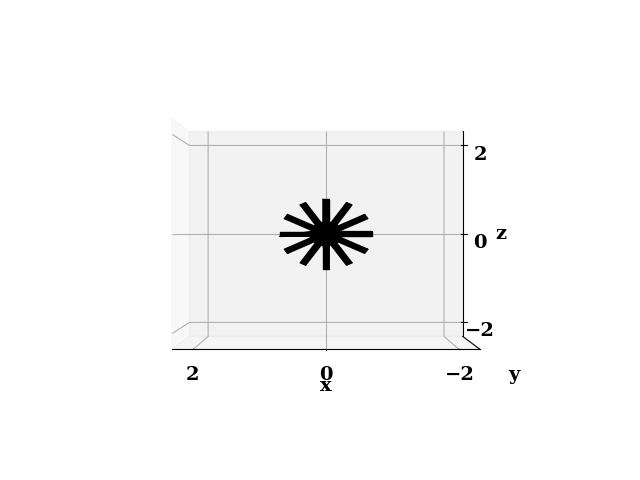
The verbose flag (-v) generates a plot of the stl mesh (as shown below)

How to change the set of shapes in the boundary patch?
Edit the json files that are read when generating the mesh. In the case tutorial_cases/loop_reactor_mixing, the boundary condition inlets consists of 3 discs
{
    "inlets": [
        {"type": "circle", "centx": 5.0, "centy": 0.0, "centz": 0.5, "radius": 0.4, "normal_dir": 1,"nelements": 50},
        {"type": "circle", "centx": 2.5, "centy": 0.0, "centz": 0.5, "radius": 0.4, "normal_dir": 1,"nelements": 50},
        {"type": "circle", "centx": 7.5, "centy": 0.0, "centz": 0.5, "radius": 0.4, "normal_dir": 1,"nelements": 50}
    ],
}
What if the STL patches overlap?
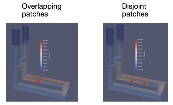
If STL patches are defined such that there is an overlap between patches, the final patch will be the union of the overlapping patches. In case of an overlap, the final patch will be therefore smaller than without an overlap. An example of this behavior is shown below for a U-loop reactor.
In this case, the inlet (highlighted in red) contain 2 circular spargers. On the left, the two spargers contain an overlap and on the right they are disjoint. The inlet patch surface area is 13% smaller on the left than the right, but both simulations successfully run.
