Meshing
Generate stirred tank reactor mesh
Generate a blockMeshDict with
inp=bird/meshing/stirred_tank_mesh_templates/base_tank/tank_par.yaml
out=bird/meshing/stirred_tank_case_templates/base/system/blockMeshDict

python applications/write_stirred_tank_mesh.py -i $inp -o $out
Then activate openFOAM environment and mesh with
blockMesh -dict system/blockMeshDict
stitchMesh -perfect -overwrite inside_to_hub inside_to_hub_copy
stitchMesh -perfect -overwrite hub_to_rotor hub_to_rotor_copy
transformPoints "rotate=((0 0 1)(0 1 0))"
Visualize mesh in Paraview

Block cylindrical meshing
Generates system/blockMeshDict
root=`pwd`
caseFolder=bird/meshing/block_cyl_cases_templates/case
mesh_temp=bird/meshing/block_cyl_mesh_templates/sideSparger

python applications/write_block_cyl_mesh.py -i $mesh_temp/input.json -t $mesh_temp/topology.json -o $caseFolder/system
Then, activate the openFOAM environment and construct the mesh with
cd $caseFolder
blockMesh
transformPoints "scale=(0.001 0.001 0.001)"
transformPoints "rotate=((0 0 1) (0 1 0))"
cd $root
Visualize the mesh in Paraview

How to change the dimensions or mesh refinement?
The geometry and the mesh size are controlled by the input file input.json.
The input file can also be in .yaml format. The parser will decide the file format based on its extension.
See bird/meshing/block_cyl_mesh_templates/baseColumn/ for an example of .yaml
How to change the arrangement of concentric cylinders?
The block topology is controlled by topology.json
We recommend always working with a schematic as shown below

The purple blocks are walls (not meshed) and the white blocks are fluid blocks (meshed). The symmetry axis is indicated as a dashed line
In topology.json, the purple blocks are defined as
"Walls": {
                "Support": [
                            {"R": 0, "L": 3},
                            {"R": 1, "L": 3}
                           ],
                "Sparger": [
                            {"R": 0, "L": 2},
                            {"R": 1, "L": 2},
                            {"R": 2, "L": 2}
                           ]
        }
How to change boundaries?
Boundaries are defined with three types, top, bottom and lateral
For example, if one wants to create a boundary called wall_sparger, shown below as the red lines

one can define the boundary as follows in topology.json
"Boundary": {
                "wall_sparger":[
                           {"type": "bottom", "Rmin": 2, "Rmax": 2, "Lmin": 2, "Lmax": 3},
                           {"type": "top", "Rmin": 0, "Rmax": 0, "Lmin": 1, "Lmax": 2},
                           {"type": "top", "Rmin": 1, "Rmax": 1, "Lmin": 1, "Lmax": 2},
                           {"type": "top", "Rmin": 2, "Rmax": 2, "Lmin": 1, "Lmax": 2}
                         ],
For lateral boundaries (called inlet in this example), and shown below as the red line

one can define the boundary as follows in topology.json
"Boundary": {
                "inlet": [
                           {"type": "lateral", "Rmin": 2, "Rmax": 3, "Lmin": 2, "Lmax": 2}
                         ],
Block rectangular meshing
Generates system/blockMeshDict
root=`pwd`
caseFolder=bird/meshing/block_rect_cases_templates/case
mesh_temp=bird/meshing/block_rect_mesh_templates/loopReactor

python applications/write_block_rect_mesh.py -i $mesh_temp/input.json -o $caseFolder/system
Then, activate openFOAM environment and construct the mesh with
cd $caseFolder
blockMesh
cd $root
Visualize the mesh in Paraview

How to change the block rectangular geometry?
The geometry of the block cylindrical mesh is defined within a 3D domain (X,Y,Z). The blocks that represent the fluid domain are a subset of a block rectangular background domain. The fluid blocks are defined using the geometry corners. For the mesh shown above, the geometry corners are the red blocks shown below
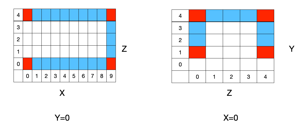
The corners are defined in input.json
"Geometry": {
        "Fluids": [
                [ [0,0,0], [9,0,0], [9,0,4], [0,0,4] ],
                [ [0,1,4], [0,4,4], [0,4,0], [0,1,0] ]
        ]
}
Related tutorials
tutorial_cases/loop_reactor_mixingtutorial_cases/loop_reactor_reacting